2. BIM: what you need to know
2.1 BIM definitions and principles
BIM, Building Information Modeling, aims to simplify the design, implementation, and operation of a construction or renovation project. It is both a “technology and associated processes for producing, communicating, and analyzing construction models” (Eastman, 2011).
ISO 29481-1:2016 defines it as: “the use of a shared digital representation of a built object to facilitate the design, construction, and operation processes so as to provide a reliable basis for decision making.”
Concretely, through the modeling and visualization of a building in 3D as a catalog of objects positioned in space and described by their properties, it is to create a digital model that supports :
- Generation of geometries (plans, sections, facades) and views without redrawing
- The automation of the various measurements and the generation of quantitative data.
- Comparison with other models (e.g. when combining the Architecture and Engineering models) to verify their concordance.
The addition of information of different natures and by successive layers, is commonly referred to as new “dimensions” added to the 3D:
- 4D (addition of implementation times) to assist Planning
- 5D for the management of quantities and associated costs (addition of prices)
- 6D for the management of facilities and assets (addition of maintenance ranges)
- Etc.1
The use of the digital mock-up does not eliminate the production and exchange of other documents. ISO/DIS 19650-1 refers more generically to an information model as “geometric models, structured data and documentation”, i.e. reports, specifications, system or component data or information, geometric data or information, etc.
What is important to remember is that the manipulation of the models is done through adapted collaborative processes and around a “common data environment”, themselves dependent on the project context:
- The organization (teams involved, roles and skills): see 2.2
- Technologies (tools used, skills available): see 2.3
- Requirements (architectural design, structural calculations, simulations…): see 2.4
The models created during a project evolve from one project phase to another. They are said to gain in “level of detail”: see 2.5
If we consider the entire life cycle of a building, BIM then breaks down into two information models:
- The project information model (PIM), fed by all the actors involved in the building’s construction (until its delivery)
- The Asset Information Model (AIM), fed by the actors involved in the operation of the building.
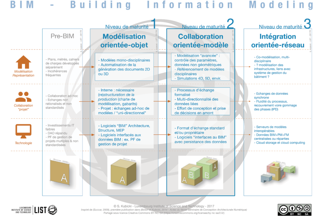
BIM maturity levels
The perspective of Luxembourg, as well as that of its neighboring countries, is to reach a level 2 BIM maturity (see diagram below). It is a question of defining processes during which each actor of the project creates his own model with the software he masters and then shares it via adapted tools. This must be done within the framework of interoperability between the different software.
Level 3 BIM, i.e. the principle of the single model, is proving difficult to implement
(both organizationally and technically) and is not a short-term objective.
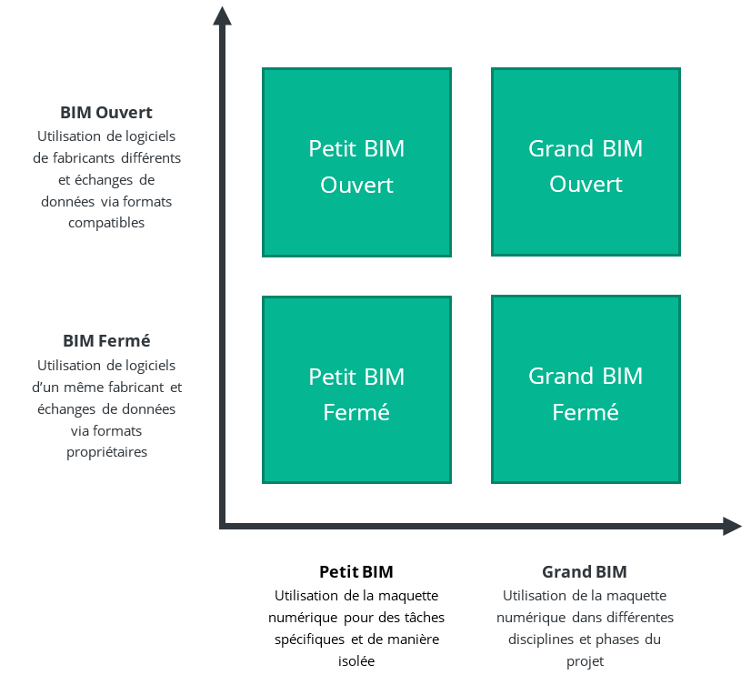
« Small BIM » / « Large BIM » – « BIM Closed » / « Open BIM »
Small BIM” is the set of technologies and processes in place to work with digital mock-up to perform specific tasks in isolation. Small BIM is therefore the working context adopted within each organization and in which they develop their own expertise. It is a matter of organizing the work of several people on the basis of established practices that are respected daily.
The “big BIM” is the set of technologies and processes in place to collaborate through the digital mock-up in a multidisciplinary context, typically throughout the life cycle of a project. The challenge here is to be able to integrate the “small BIMs” of each of the organizations involved in a functional manner and depending on the objectives in order to ensure collaboration between them. The big BIM is therefore something that varies and needs to be redefined for each project.
“Closed BIM” is provided by software from the same manufacturer and which therefore have proprietary features and exchange formats ensuring (almost) total compatibility between them. Closed BIM is therefore to be preferred to avoid interoperability problems.
“Open BIM” is the term used to describe the use of software from different manufacturers and therefore the exchange of data via compatible exchange formats and adapted import/export functions. The universal standardized format for open BIM exchange is IFC.
As shown in the diagram below, “Small -” and “Large BIM” as well as “Closed BIM” and “Open BIM” are concepts that combine and create four different working contexts.
2.2 The roles of BIM
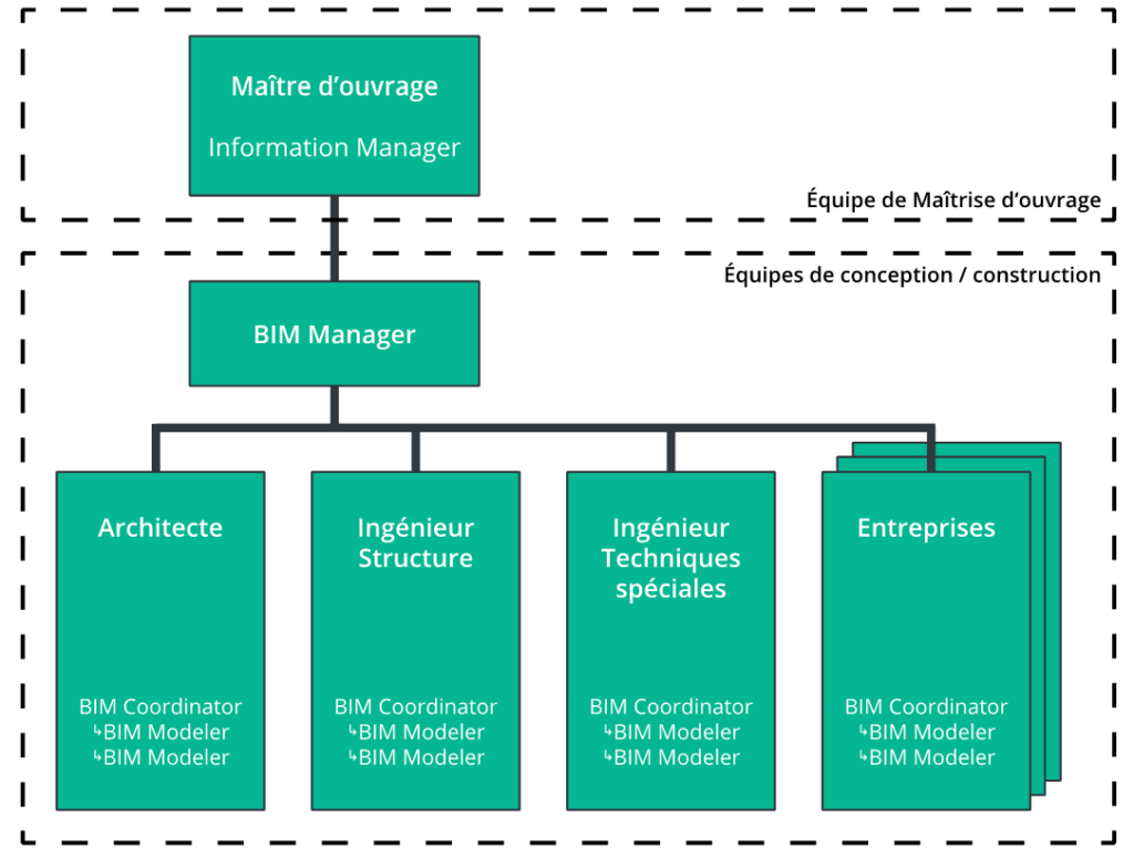
Typical organizational chart
The efficiency of BIM implies a mastery of the tools AND methods that are specific to it. BIM Management” of a project in the broadest sense of the word, implies “new roles” that complement/integrate the organization, whether on the side of the project owner or the project manager and contractors.
On the owner’s side:
- The “Information Manager”: he/she formalizes the project owner’s requirements and then verifies the conformity of the delivered information with these requirements (see 3.1). He/she must therefore understand the project owner’s needs and be able to make the necessary technical implementations (e.g. setting the parameters of the collaborative platform, checking the models, etc.)
On the design/build team side:
- The “BIM Modeler” or BIM Modeler: he is the “evolution” of the designer2 and must be trained to master 3D drawing tools such as Revit, Archicad, Allplan, etc. He is responsible for providing a geometrically accurate model but also the right information according to the needs. He is responsible for providing a geometrically accurate model but also the right information according to the needs. It is therefore a profile above all “technical”: it must be adequately trained (BIM modeling software and collaborative platforms).
- The “BIM Coordinator” is responsible for supervising the BIM Modelers of his organization, checking the accuracy of the models (of his organization), and ensuring their exchange with other organizations. He must therefore combine technical and managerial skills within his activity. This implies a good mastery of modeling tools but also of model checking and sharing/collaboration.
- At the project management level, the coordinators must provide the coordinated deliverables of the design team. As such, a “referent” can be chosen among the BIM coordinators to represent the design team to the BIM Manager of the project (see definition below) and to be the main contact.
- Some construction teams will also have digital information to add to the project. As such, they will be subject to the same rules as the prime contractor and will have to report to the BIM Manager on their work on the digital model.
- The “BIM Project Manager” or BIM Manager: he writes the “BIM Execution Plan” of the project which governs the project in accordance with the requirements of the client. He verifies compliance by receiving deliverables from the various BIM coordinators. The role of the BIM Manager is to be distinguished from that of the project manager: it is not a decision-making role but rather one of audit and advice. Its scope of intervention is limited to the integrity of the BIM models, the analysis and the analysis and exploitation of these models is carried out by the people in charge of the project (OPC synthesis, project manager…). However, the BIM Manager must have experience with the construction project as a whole in order to understand the progress of the different phases. From a technical point of view, he has the ability to analyze a digital model via dedicated software. He/she may also be required to provide support as a companion, for example to the different BIM coordinators for the good follow-up of the BEP (settings, etc.) NB: the tasks of the BIM Manager are varied, so it is not excluded that they are dedicated to a “BIM Management team” and not to a single person.
Note: not all repositories adopt the same vocabulary when describing roles. The terms used here are therefore a syntactic bias that seems consistent and follows the majority of repositories.
Assigning roles
BIM-related roles are assigned according to the skills and context of the project.
The above organization chart is in no way representative of a particular contractual framework (separate contracts, design & build, etc.). So, depending on the context, the tasks relating to these different roles may be allocated differently. For example, the role of BIM Manager may be taken on in whole or in part by one of the design teams. It can also be “outsourced” to an independent office. The same applies to the Information Manager on the project owner’s side.
| BIM Modeler | BIM Coordinator | BIM Manager | Information Manager | |
|---|---|---|---|---|
| Framing of requirements MO (Project BIM Brief – PBB) | Analysis of requirements in PBB for drafting the BEP | Drafting requirements in the PBB | ||
| Setting up the project (BIM Execution Plan – BEP) | BEP follow-up | Provision of certain inputs required for writing the BEP. Follow-up of the BEP. | Drafting the BEP | Verification and validation of the BEP |
| Mastery of modeling modeling tools | According to his office | According to tools. Mastery of IFC exchanges | Technical luggage to bring support support when needs | According to MO tools |
| Mastery of tools exchange | Use of tools throughout organization | Use of tools throughout organization | Use and management of tools | Use and management of tools |
| Mastery of tools supervision | Applications pour vérifier le modèle | Use and management/parameterization of tools (checking project rules) | Use and management/setting of tools (checking rules rules) | Operation and management / configuration of tools (control rules specific to needs) |
2.3 BIM software and formats
Data modeling and processing software
To create the digital mock-up, it is necessary to use modeling software that not only allows you to draw in 3D, but also to identify and characterize the objects created with different information. There are several different modeling software packages available, all offering equivalent functionality, although each may differ from its competitors in certain respects. The IFC format is a universal exchange format for exchanging and working on models, regardless of the modeler used.
In addition to modeling software, other tools can be used to manipulate BIM data, whether for verification, calculation, reporting or other purposes. The use of BIM does not preclude the use of 2D drawings, particularly for the creation of complex details (e.g. waterproofing connection details, special parts to be integrated into a formwork, complicated corners for reinforcement, etc.). Be careful, however, how you proceed: export a 2D view and editing it in a drawing program will create the required detail, but it will no longer be associated with the model. Any modification to one will then have no impact on the other. To maintain this link, the detail must be created in the modeling software itself, by superimposing it on the model.
IFC (“Industry Foundation Classes”): the “open BIM” exchange format
The IFC format is an exchange format created to ensure interoperability between software programs, enabling the universal description of the “elements” that make up a building throughout its life cycle (design, construction, operation) and from different points of view (architectural, structural, thermal, estimating, etc.). IFCs are included in a file whose format is predefined according to an international standard (STEP) ISO 10303-21.
By “elements” we mean the spaces and groups of spaces that structure the building (room, zone, floor, site, etc.) and the objects that define and compose them (architectural structures, technical equipment, furniture, etc.). For each element, IFC properties thus provide information on its form (or representation), its characteristic information and its relationships with other elements.
Since 2013, the IFC format has been standardized to ISO 16739:2013 (“Industry Foundation Classes (IFC) for data sharing in the construction and facility management industries”).(http://www.iso.org/iso/catalogue_detail.htm?csnumber=51622)
Useful links
http://bimstandards.fr/
http://standards.buildingsmart.org/IFC/RELEASE/IFC4/ADD2_TC1/HTML/
https://standards.buildingsmart.org/IFC/RELEASE/IFC2x3/TC1/HTML/
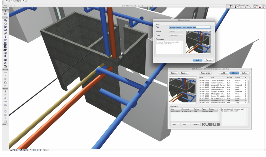
BCF (BIM Collaboration Format): the communication format for models
BCF (BIM collaboration format): the communication format for modelsIt enables the transfer of comments relating to an object in a model between the various participants in a project. Thanks to the BCF format, viewpoints, selected objects, snapshots and comments are directly retrieved in any modeling software for direct modification according to the problem communicated.
Collaborative platforms (the Common Data Environment)
To enable several people to work together on models and exchange documents, it is necessary to set up an appropriate collaboration methodology around a “common data environment” (CDE), a central repository where information relating to construction projects is stored and linked together. The content of the CDE is not limited to deliverables created in a “BIM environment”: it includes documentation, the geometric model and non-geometric elements.
Collaborative platforms, already well known for document exchange and workflow management in the construction industry, can be adapted to share models and visualize the information they contain. Centralizing exchanges is essential to ensure that information is properly transmitted between project teams AND to the client. It will also enable the BIM Manager to have an overview of project activity and facilitate his mission.
A CDE needs to be organized into workspaces, so that files can be moved from one status to another, and access can be given to the right people as required. A typical CDE structure for sharing models is as follows:Work in progress: for information in progress and unverified data (one space per team)
Shared: for information shared between several design/build teams, who will use it to coordinate their work (e.g. coordination of mock-ups and clash detection) and as a basis for further work (e.g. sharing the architectural mock-up as a basis for the structural mock-up). In this area, the BIM Manager can review and approve the conformity of the information with the project’s BEP.
This space is not visible to the project owner. If it is necessary to distribute unfinalized working documents to the Owner, then it is recommended to use a second shared space (“shared with the Owner”). Otherwise, use the “published” space below.
Published: The information has been validated by the BIM Manager and is accessible to all other stakeholders. It is used to generate project deliverables (e.g. models, plans and other submission documents).
Archiving: Data is archived when it is no longer needed, but remains available. When sharing layouts, it is important to control their size. Working with files that are too large can cause problems. The “Architecture”, “Techniques” and “Structure” models can be split up as required:
according to the elements to be modeled, or by batch (e.g. by separating furniture into a separate model)
According to the structure of the project itself (e.g. in the case of a project comprising several buildings: one model for each building).
Another essential feature of CDE is its ability to manage and track different versions of a file (i.e., to monitor their sharing, downloading, updating, etc.).
2.4 The uses of BIM
It’s not a question of doing everything with BIM; you have to choose what BIM is going to be used for during the project, depending on the specifics of the project, whether in terms of objectives or skills. In other words, you need to define which uses of BIM are going to be implemented (see also Penn State CIC’s document “The uses of BIM”). : http://bim.psu.edu/Uses/the_uses_of_BIM or chapter 3.4 of Mediaconstruct’s “Guide méthodologique de rédaction d’une convention BIM”: http://www.mediaconstruct.fr/travaux/guide-de-convention-bim).
The choice of these uses is made at the outset of a project, and from these uses flow the work processes put in place (see chapter 2). It must therefore be clearly defined and agreed by all project stakeholders. The skills and tools available must enable the chosen uses to be implemented.
We can list 21 typical uses:
- 01. Programming
Use of BIM to link an operation’s program with future digital models. This makes it possible to integrate the project owner’s requirements, to facilitate their consideration by the project owner and to carry out conformity checks. - 02. Analysis and modeling of existing (site + buildings)
Use of a precise digital survey of the various existing structures and the site to create an accurate model as a starting point for a new project. - 03. Architectural design
Use consisting in creating an “architectural” model to define the designed spaces. This model will evolve throughout the project, and will serve as a basis for the work of engineers during technical and structural studies. - 04. Building systems design
Use consisting of creating a “structural” model to define construction systems. This model will evolve throughout the project, based on the choices made and the evolution of the architectural model. - 05. Technical systems design
Use consists of creating a “special techniques” model to define technical systems. This model will evolve throughout the project, based on the choices made and the evolution of the architectural model. - 06. Project review, 3D coordination (“clash detection”)
The practice of superimposing models to gain an overview of the project as a whole, and to help it evolve in the light of the coordination problems that emerge. Detecting collisions (“clashes”) between models is part of this practice. - 07. Production of deliverables (geometrical, views, quantities, etc.)
Use the digital mock-up as the basis for producing traditional project deliverables: plans of all kinds, sections, elevations, perspectives, quantities, etc. Tender forms can also be extracted from the digital mock-up. - 08. Cost estimates
Used to estimate project costs by linking the quantities extracted from the digital mock-up to a financial basis in order to simulate project costs (requires modeling adapted to the extraction of the necessary quantities). - 09. Evaluations/simulations of comfort performance (thermal, luminosity, acoustic, etc.)
Use of the model to simulate future building performance, such as heat transfer, luminosity and acoustics. The aim is to check compliance with requirements and modify the design if necessary. - 10. Stability performance assessments/simulations
Use of the model to simulate future building performance, such as load transfer and stability of load-bearing elements. The aim is to check compliance with requirements and modify the design if necessary. - 11. Building environmental impact assessments/simulations
Use of the model to assess the building’s environmental impact in terms of materials used, simulated energy consumption and recycling opportunities during demolition. It can also be used, for example, to list potentially harmful products. - 12. Verification of standards, Checking compliance with requirements or constraints
Use of a model to check that the project complies with pre-established standards and regulations (e.g. accessibility for the disabled). This verification is carried out using automated checking rules. - 13. Simulation of the construction and/or demolition process: 4D planning
Use to virtually simulate the progress of a project by associating the model with a Gantt-type schedule. This schedule can be roughly pre-established during the design phase, and then become more precise during the construction phase. Coupled with the “cost estimation” function, it can be used to manage the financial progress of the project. - 14. Simulation of construction and/or demolition site implementation
Virtual simulation of site layout (temporary structures, waste storage, etc.) and logistics (supplies, orders, stocks, etc.) to optimize available space, resources and implementation times. - 15. Prefabrication
Use consisting in the precise modeling of certain elements, defining the templates and cut-outs required for prefabrication and installation on site. The “prefabrication” usage is similar to construction simulation usages 13 and 14, but involves a higher level of detail in the elements to be prefabricated. - 16.Consolidation of digital mock-ups and documents, final digital mock-up
Use consisting in updating the final model (geometry + information) and the associated corpus of documentation in order to deliver them to the project owner as an “As-Built” file. - 17.Provisional maintenance plan (definition of maintenance ranges)
Use of the information contained in the operating model to set up a maintenance plan for the building’s various components throughout its life cycle. - 18. Analysis of actual project performance
Use consisting in supplementing the operating model with actual values measured in the building (consumption, temperatures, luminosity, air flow rates, etc.). These values can be compared with those estimated in the design phase on the basis of simulations (see uses 9 to 11). - 19. Plant and equipment management (CMMS)
Use consisting in linking an operating model to a CMMS system, in order to use the information it contains to plan and manage maintenance operations, whether preventive or corrective. A two-way link will enable the model to be updated with information gathered at the end of maintenance operations. - 20. Space management and allocation (occupancy, moves, etc.)
Usage consisting of linking an operating model to a space management system in order to exploit the information it contains to plan and manage building occupancy, moves, furniture, etc…. A bilateral link will enable the model to be updated with information gathered after changes have been made. - 21. Project media (images, videos, virtual tours, etc.)
The model is used to present the project using images and videos to explain its architectural and technical concepts. With the help of advanced technical equipment, virtual tours can also be envisaged.
2.5 The “levels” of a BIM digital model
The basic concept of “LOD” for Level of Development has evolved considerably over the years, and has been interpreted in a number of different ways, notably through the introduction of various national guides, including the present “Luxembourg BIM Application Guide”. Today, the “Level of …” is thus varied and the subject of several different definitions – so much so that one comes to speak of a general concept of “LoX” (for more information on this subject, see the article “The many faces of ‘LOD'” by Marzia Bolpagni).
According to ISO/DIS 19650-1, a “level of information need” should be defined, i.e. the quality of each piece of information to be delivered in terms of granularity to serve the purpose for which the information is required, and no more. There are then a number of measurement quantities, which may be complementary but independent, but which make it possible to define the granularity and level of the information requirement that needs to be defined.
The level proposed in this guide as the Luxembourg national level follows this approach: called the “GID level”, it is the addition of three granularity levels relating to Geometry (100/200/300/400/500), Information (10/20/30/40/50) and Documentation (1/2/3/4/5).
The addition of the documentation level to the traditional “Geometry & Information” 4 is a specificity that takes into account both the current skills of the sector and the limits of available software: as the BIM production capability is not the same for everyone, we need to be able to find an alternative to modeling that enables us to deliver “less detailed” models, but supplemented by additional documents (2D detail, photo, catalog reference, technical data sheet, etc.) as required.
In this way, the GID concept takes into account all the data required and shared during the course of a project: “geometric models, structured data and documentation” (see 2.1).
What’s more, the division into three distinct parts offers a high degree of flexibility for project-specific adjustments. So, for example, if it is agreed that the common GID level in the APD phase is 222, you can vary the G geometry level from 200 to 300, giving a total GID of 322.
The table below details what these levels and their values correspond to. The GID sheets (appended to this document) will help you understand exactly what these levels correspond to for each object to be modeled. The project phases associated with each level are reference phases: this association is by no means restrictive, and may vary according to your needs.

Note: Level 0 can be used to indicate that nothing is expected for one or two of the three parameters.
three parameters (e.g. 300 = a detailed 3D drawing with no added information or documentation, 055 = a cobie).